
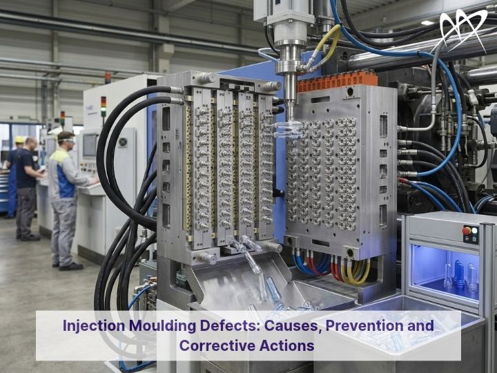
Injection moulding can produce highly repeatable plastic components, but consistent output depends on the interaction between mould design, material, machine settings, cooling, tooling condition, and process control. When one factor moves outside the intended range, defects can appear as short shots, flash, sink marks, warpage, weld lines, burn marks, flow marks, or dimensional variation.
A systematic approach to Injection Moulding Defects helps manufacturers identify whether a problem is related to the Injection Mould, material preparation, Injection Moulding Machine settings, or the overall Injection Moulding Process. Understanding the visible symptom is only the starting point; the corrective action should address the underlying cause rather than simply changing machine parameters.
What Are Injection Moulding Defects?
Injection moulding defects are visible or measurable imperfections that occur when plastic does not fill, cool, solidify, or eject as intended. Some are mainly cosmetic, while others can affect dimensions, strength, assembly, sealing, or product performance.
A useful troubleshooting process starts by identifying what the defect looks like and where it occurs. For example, a short shot can indicate insufficient filling, restricted flow, inadequate temperature, poor venting, or insufficient pressure. Warpage, by contrast, is often connected to uneven cooling, shrinkage, part geometry, or residual stress.
Because similar symptoms can have different causes, corrective action should be based on process evidence rather than simply increasing temperature or pressure.
Common Injection Moulding Defects, Causes and Corrective Actions
1. Short Shot
A short shot occurs when molten plastic does not completely fill the cavity before the material freezes or the cycle ends. The result may be an incomplete part or missing features.
Common causes: insufficient injection pressure or speed, low melt temperature, restricted gates or runners, poor venting, excessive flow resistance, or unsuitable material condition.
Corrective actions:
-
Check melt and mold temperature.
-
Review injection speed and pressure.
-
Inspect gates, runners, and nozzles.
-
Check venting near the end of the flow path.
-
Review cavity filling balance.
If the defect repeatedly appears in the same cavity or location, the mould should be inspected rather than continuing to change machine settings.
2. Flash
Flash is excess plastic along the parting line, around inserts, or near areas where the mould should close tightly. It can affect appearance and assembly.
Common causes: excessive injection or holding pressure, mould-clamping problems, worn parting surfaces, poor alignment, excessive material temperature, or inadequate support.
Corrective actions:
-
Inspect parting surfaces and alignment.
-
Check mould wear or damage.
-
Review injection and holding pressure.
-
Confirm appropriate clamping conditions.
-
Check material processing temperature.
Recurring flash at the same location can indicate a tooling issue.
3. Sink Marks
Sink marks are shallow depressions commonly found over thicker sections, ribs, or bosses. They occur when the outer surface solidifies while material underneath continues to shrink.
Common causes: excessive wall thickness, insufficient packing or holding pressure, inadequate holding time, high mould temperature, or poor cooling around thick sections.
Corrective actions:
-
Review wall and rib geometry.
-
Improve cooling around thick areas.
-
Optimize holding pressure and time.
-
Check gate location and packing effectiveness.
-
Review the mould design if the defect persists.
4. Warpage
Warpage occurs when a moulded part bends, twists, or develops dimensional deviations during or after cooling. Uneven cooling is a common contributor, but shrinkage, part geometry, material orientation, residual stress, and unbalanced filling can also contribute.
Corrective actions:
-
Check cooling balance across the mould.
-
Review filling and packing balance.
-
Inspect large wall-thickness differences.
-
Evaluate mould temperature stability.
-
Check ejection conditions.
For dimension-critical components, cooling design should be considered alongside processing parameters.
5. Weld Lines
Weld lines form when two melt fronts meet after flowing around an obstacle such as a core, hole, insert, or cavity feature. Their visibility and strength implications depend on the material and process conditions.
Their location is influenced by gate position, flow path, melt temperature, injection speed, venting, and part geometry.
Corrective actions:
-
Review gate position and flow direction.
-
Optimize injection conditions within the material's processing window.
-
Improve venting where trapped air contributes to poor fusion.
-
Review part design if the weld line occurs in a critical area.
-
Use mould-flow analysis during design development where appropriate.
The objective is often to position the weld line away from critical functional areas rather than trying to eliminate every weld line.
6. Burn Marks
Burn marks are dark or discoloured areas generally associated with trapped air or gases that become compressed and overheated during filling. They often appear near the end of filling or around deep features.
Common causes: inadequate venting, excessive injection speed, trapped air, or thermal degradation.
Corrective actions:
-
Inspect and improve venting.
-
Review injection speed.
-
Confirm appropriate material temperature.
-
Check vents for blockage or contamination.
-
Review the flow path if the defect repeatedly occurs in one location.
7. Flow Marks
Flow marks appear as lines, ripples, or surface changes caused by variations in how molten plastic flows and cools against the cavity surface.
They can be associated with injection speed, melt temperature, mould temperature, gate design, flow resistance, or wall-thickness changes.
Corrective actions:
-
Review injection speed and melt temperature.
-
Check mould temperature stability.
-
Inspect gate condition and location.
-
Review wall-thickness transitions.
-
Confirm the cavity surface has the intended finish.
A surface defect should not automatically be treated as a polishing problem; its flow and thermal causes should also be investigated.
How Mould Design Influences Injection Moulding Defects
An Injection Mould is more than a cavity that gives plastic its final shape. Gate location, runner layout, venting, cooling, cavity geometry, parting surfaces, ejection, and dimensional accuracy all influence how the Injection Moulding Process behaves.
For high-volume packaging, these relationships become especially important because a small tooling variation can be repeated across a large production quantity.
Dowell Moulds' Injection Mould solutions cover factors such as dimensional accuracy, surface finish, cooling performance, component fitment, and production readiness. These considerations can help identify tooling-related sources of variation before the mould enters production.
For applications requiring controlled material flow across multiple cavities, Hot Runner Moulds may also be relevant. Hot runner systems maintain heated material flow and can reduce runner waste, while balanced temperature control and gate design remain important for consistent filling.
Injection Moulding Machine Settings vs Mould Problems
A common troubleshooting mistake is assuming every defect is caused by the Injection Moulding Machine. Machine parameters affect filling, packing, cooling, and ejection, but the mould can introduce its own limitations.
A restricted gate, blocked vent, unbalanced runner, poor cooling layout, damaged parting surface, or incorrect cavity geometry cannot always be corrected through machine settings.
A practical troubleshooting sequence is:
-
Identify the exact defect and location.
-
Check whether it occurs in one cavity or multiple cavities.
-
Compare the defect across production cycles.
-
Review material preparation and machine parameters.
-
Inspect gates, vents, cooling, parting surfaces, and ejection components.
-
Make one controlled change at a time.
-
Validate the result over representative production cycles.
This approach makes it easier to distinguish a process-setting issue from a tooling-related problem.
Prevention: What Should Manufacturers Check Before Production?
Defect prevention starts before the first production run. During mould development, manufacturers should consider product geometry, material, production volume, gating, cooling, venting, ejection, and dimensional tolerances.
Mould-flow analysis can help evaluate filling behavior, pressure requirements, weld-line locations, air traps, cooling, shrinkage, and potential warpage before mould manufacturing is completed.
Precision machining is equally important. CNC and EDM processes need to reproduce approved cavity and component geometry accurately, while inspection should verify critical dimensions, alignment, surface condition, and fit.
For manufacturers interested in the relationship between machining precision and mould performance, Dowell's article on CNC and EDM machining for plastic mould accuracy provides additional technical context.
Trial moulding is another important validation step. A mould should be tested under representative conditions so filling, flash, surface finish, cooling, ejection, dimensional consistency, and cycle performance can be evaluated before sustained production.
Common Troubleshooting Mistakes to Avoid
Several troubleshooting habits can make injection moulding defects harder to solve:
-
Changing multiple machine settings simultaneously, making the result difficult to interpret.
-
Increasing injection pressure repeatedly when the underlying problem is restricted flow or poor venting.
-
Ignoring cavity-to-cavity differences in multi-cavity moulds.
-
Treating warpage only as a material problem without checking cooling and part geometry.
-
Polishing a surface defect without investigating its flow or thermal cause.
-
Continuing production with a recurring tooling defect without inspecting the mould.
-
Skipping mould trials or dimensional validation before high-volume production.
The objective should be a repeatable process, not simply one acceptable sample.
When to Involve an Injection Mould Manufacturer
If a defect repeatedly occurs at the same cavity location, continues after reasonable process adjustments, or appears across multiple production runs, the tooling should be reviewed by an experienced Injection Mould Manufacturer.
A technical review can examine cavity geometry, gate and runner configuration, cooling channels, venting, parting surfaces, ejection, cavity balance, and component wear. For new projects, involving the mould manufacturer during design development can also help identify production risks before the tool is manufactured.
Dowell Moulds has manufactured plastic packaging moulds since 2002 and works with injection moulds, PET preform moulds, cap moulds, compression moulds, and blow moulds. Its manufacturing process includes design validation, precision machining, assembly, inspection, and production-readiness checks.
For buyers evaluating an Injection Moulding Supplier, useful criteria include engineering capability, mould-design experience, CNC and EDM infrastructure, inspection procedures, trial practices, technical support, and experience with comparable applications.
Final Takeaway
Injection moulding defects should be treated as process-diagnosis problems rather than isolated cosmetic issues. Short shots, flash, sink marks, warpage, weld lines, burn marks, and flow marks can have different causes, and the same visible defect may result from more than one process or tooling condition.
The most reliable approach is to examine the defect's location and pattern, review material and machine conditions, inspect the injection mould, and make controlled changes. Good mould design, balanced cooling, appropriate venting, accurate machining, and proper trial validation can reduce the risk of recurring defects before full-scale production begins